What Is a Heavy Duty Gear Motor and How Does It Work?

Time:2026-10-12 Author:Sienna
0%

A Heavy Duty Gear Motor combines an electric motor with a geared transmission. It delivers controlled torque for demanding industrial work. Think of a conveyor carrying wet aggregate, not a laboratory test bench. The motor creates rotation. The gearbox reduces speed and multiplies torque. This combination helps equipment start under load and operate steadily for long periods.

The International Energy Agency reports that electric motor systems consume a significant share of global electricity, making efficiency a practical business concern (IEA, Energy Efficiency 2023). The U.S. Department of Energy also notes that motor-driven systems can represent over half of industrial electricity use (U.S. DOE, Motor Systems Tip Sheet). These figures explain why gear ratio, motor efficiency, thermal management, and maintenance deserve close attention. A larger motor is not automatically a better motor. That assumption often creates unnecessary energy costs.

Austin Hughes, author of Electric Motors and Drives, states, “A motor is a device for converting electrical energy into mechanical energy.” His definition is simple, but it frames the entire system. A Heavy Duty Gear Motor adds mechanical advantage through reduction gearing. Engineers must still match torque, speed, duty cycle, shock loading, lubrication, and enclosure protection. Small details matter. A misaligned coupling can produce vibration, heat, and premature bearing failure. In practice, selecting the correct unit is less about maximum horsepower and more about real operating conditions. Even experienced teams can overlook starting torque or uneven loading. This guide examines how these motors work, where they perform best, and why reliable specifications matter.
What Is a Heavy Duty Gear Motor and How Does It Work?

Definition and Core Purpose of a Heavy Duty Gear Motor

A heavy-duty gear motor is an integrated drive unit designed to produce controlled torque under demanding conditions.

It combines an electric motor with a gearbox in one compact assembly. The motor creates rotational energy, while the gearbox reduces speed and increases usable torque. Its core purpose is simple: move heavy loads steadily and safely.

Not merely more power.

The gearbox also improves control. For example, a conveyor may need slow movement with strong pulling force. A direct-drive motor could rotate too quickly or struggle during startup. Gear reduction helps the system handle that resistance.

In field maintenance, technicians often inspect oil condition, shaft alignment, mounting bolts, and unusual vibration. Small changes can reveal serious internal wear.

A heavy-duty design usually includes stronger gears, reinforced bearings, durable housings, and improved heat management. These features support long operating cycles, frequent starts, and dusty or humid workplaces.

However, “heavy-duty” is not a universal guarantee. The correct unit still depends on load weight, speed, duty cycle, shock levels, and installation position.

I have seen equipment fail because its motor was powerful enough, but the gearbox ratio was poorly selected. That mistake is easy to overlook.

Proper sizing should consider starting torque, service factor, ambient temperature, and maintenance access before installation.

Main Components and Their Functions

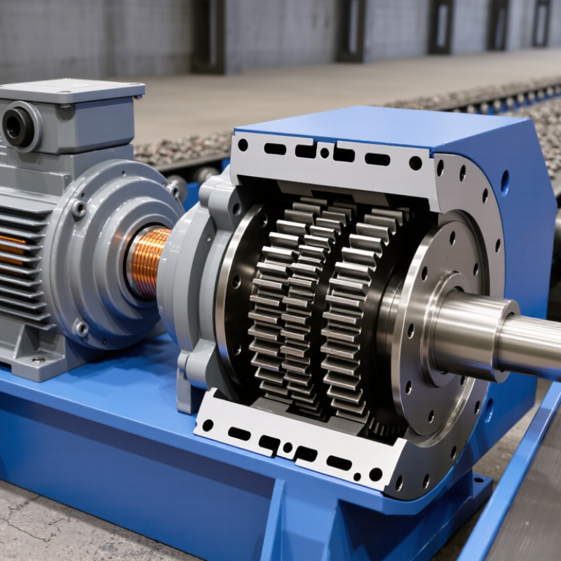
A heavy duty gear motor combines an electric motor with a mechanical gearbox. The motor creates rotational force. The gearbox reduces speed and increases torque for demanding equipment. This arrangement helps conveyors, mixers, lifts, and automated gates move heavy loads steadily.

The motor usually includes a stator, rotor, windings, and cooling system. The stator creates a magnetic field around the rotor. Electrical energy makes the rotor turn. A fan, fins, or external cooling circuit removes heat from continuous operation. Heat remains a serious concern. I have seen oversized motors fail early because poor ventilation trapped heat around the housing.

Inside the gearbox, multiple gears transfer motion through carefully selected ratios. Smaller input gears turn larger output gears, increasing torque while lowering speed. Hardened shafts carry this force to the output connection. Bearings support the shafts and limit friction. Seals help retain lubricant and block dust or moisture. The housing protects these parts and keeps them aligned under load. Some systems also include a brake, encoder, or overload sensor for controlled stopping and safer operation.

Lubrication is not a minor detail. Incorrect oil levels can damage teeth and bearings. Regular inspections should check vibration, noise, temperature, leaks, and mounting bolts. A quiet motor is not always healthy. Subtle vibration may reveal misalignment before visible damage appears. Gear selection also deserves careful review, because real loads often exceed the original estimate.

How a Heavy Duty Gear Motor Transmits Power

What Is a Heavy Duty Gear Motor and How Does It Work?

How a Heavy Duty Gear Motor Transmits Power

A heavy duty gear motor combines an electric motor with a gear reducer. The motor creates rotational force at high speed. The gearbox then lowers speed and increases usable torque. This conversion lets conveyors, mixers, lifts, and processing machines move heavy loads with controlled motion.

Power travels through the motor shaft into the first gear stage. Smaller teeth drive larger gears, reducing rotational speed at each stage. The final output shaft turns more slowly but delivers stronger torque. Helical, planetary, or spur gears may be used, depending on load direction, space, and required efficiency. Bearings support the shafts and keep gear alignment stable.

In field inspections, heat often reveals transmission problems before noise becomes serious. Poor lubrication increases friction between teeth. Misalignment can damage bearings and create uneven tooth wear. A correct torque calculation must include starting loads, shock loads, and duty cycles. A motor that works on paper may still struggle during frequent starts. That detail is easy to miss. Housing strength, sealing, and mounting also affect performance in dusty or wet workplaces. Regular oil checks and vibration measurements provide practical evidence of condition, although they cannot replace a full inspection.

What Is a Heavy Duty Gear Motor and How Does It Work? - How a Heavy Duty Gear Motor Transmits Power

Power-Transmission Element Primary Function Typical Engineering Data How It Transmits Power Heavy-Duty Design Considerations
Electric Motor Converts electrical energy into rotational mechanical energy. Common industrial motor speeds include approximately 1,450 rpm at 50 Hz for a four-pole motor and approximately 1,750 rpm at 60 Hz. The motor shaft supplies input speed and torque to the gearbox. The motor must be selected for continuous duty, starting torque, thermal load, enclosure requirements, and the available power supply.
Input Coupling or Pinion Connects the motor shaft to the first reduction stage. Must be rated for the motor torque, starting loads, shock loads, and permissible shaft misalignment. Transfers rotary motion into the gearbox without directly changing the motor speed unless an additional transmission is used. Flexible couplings can reduce the effects of minor alignment errors and torsional vibration.
Gear Reduction Stages Reduce rotational speed and increase output torque. Overall reduction ratios commonly range from about 3:1 to more than 100:1, depending on the gearbox design and number of stages. A smaller driving gear turns a larger driven gear. Multiple stages multiply the speed reduction and torque increase. Gear teeth, shafts, bearings, and housing must withstand continuous torque, impact loading, fatigue, and heat generation.
Gears Change speed, torque, and sometimes the direction of rotation. Typical single-stage efficiencies are approximately 90–98% for well-designed spur or helical gear stages and approximately 90–97% for many planetary stages. The gear ratio is determined by the number of teeth: Ratio = driven-gear teeth ÷ driving-gear teeth. Hardened or case-hardened teeth, accurate tooth geometry, and effective lubrication improve wear resistance and load capacity.
Bearings and Shafts Support rotating parts and carry radial and axial loads. Load capacity depends on bearing type, shaft diameter, operating speed, duty cycle, and the external overhung load. Bearings maintain gear alignment while shafts transfer torque between the motor, gears, and driven machine. Heavy-duty units require suitable bearing life, shaft strength, sealing, and protection from contamination.
Gearbox Housing Encloses and aligns the gears, shafts, bearings, and lubricant. Common materials include cast iron, steel, and aluminum alloys; the selected material depends on torque, weight, vibration, and environmental conditions. Maintains the fixed center distances needed for the gears to mesh correctly under load. A rigid housing helps control deflection, noise, vibration, and lubricant leakage.
Lubrication System Reduces friction, removes heat, and protects contacting surfaces. Oil or grease selection depends on speed, load, temperature, gear type, and the manufacturer’s lubrication requirements. A lubricant film separates metal surfaces and reduces power losses caused by friction and wear. Correct oil level, viscosity, sealing, and scheduled inspection are essential for continuous high-load operation.
Output Shaft Delivers the reduced-speed, higher-torque rotation to the driven equipment. Output speed is approximately: Motor speed ÷ Gear ratio. The shaft transfers torque through a keyway, spline, flange, hollow bore, or another mechanical connection. The connection must handle rated torque, transient torque, radial loads, axial loads, and the required duty cycle.
Seals and Protection Prevent lubricant loss and keep dust, moisture, and contaminants away from internal components. Protection level is specified by the enclosure rating and application requirements; common industrial motor enclosures use protected designs such as IP55 or higher. Seals maintain the internal lubricant environment while allowing the shaft to rotate. Seal material and protection should match temperature, chemicals, washdown conditions, dust, and outdoor exposure.
Power and Torque Relationships
  • Output speed: nout = nmotor ÷ i
  • Approximate output torque: Tout = Tmotor × i × η
  • Motor torque from power: T = 9550 × P ÷ n, where torque is in N·m, power is in kW, and speed is in rpm.
  • Example: A 1.5 kW motor running at 1,450 rpm with a 20:1 gearbox and 94% gearbox efficiency produces approximately 72.5 rpm output speed and 186 N·m output torque.

Common Gear Types and Motor Configurations

A heavy-duty gear motor combines an electric motor with a gearbox. The motor supplies rotation, while the gears reduce speed and increase torque. This arrangement helps equipment move heavy loads with controlled force. In maintenance work, gear selection often matters more than motor size alone.

Helical gears provide smooth, quiet operation and suit conveyors or mixers. Bevel gears redirect power through an angle, making them useful in compact drive systems. Worm gears offer high reduction in a small space, but they may lose more energy as heat. Planetary gears distribute load across several gears. They support high torque in demanding machinery. Each type has limits. A design that works well on paper may still struggle with shock loads or poor lubrication.

Motor configurations also change performance. A three-phase motor usually supports steady industrial operation, while a single-phase motor fits lighter-duty equipment. Brake motors help stop moving loads quickly. Variable-speed drives allow operators to adjust output for changing production needs. Tips: Check torque, duty cycle, mounting position, and gearbox temperature before installation. Keep the shaft aligned. Check the load twice. A common mistake is choosing by horsepower alone; starting torque and daily operating hours deserve equal attention.

Industrial Applications and Selection Factors

A heavy duty gear motor combines an electric motor with a gearbox built for high torque, repeated loading, and harsh industrial conditions. The motor creates rotation, while the gears reduce speed and multiply torque. A conveyor may move slowly, yet still start with a fully loaded belt. That is the practical advantage.

Industrial use requires more than matching horsepower. The U.S. Department of Energy’s Industrial Motor Systems Market Assessment estimated that motor-driven systems consumed about 69% of manufacturing electricity. This older benchmark still shows why efficiency matters.

Engineers should examine duty cycle, start frequency, shock loads, ambient temperature, and required output speed. Food-processing lines may need washdown protection. Aggregate equipment may require sealed housings and stronger bearings. Oil mist, dust, and poor alignment can shorten service life quickly.

Selection also depends on gearbox ratio, service factor, mounting position, shaft design, braking needs, and thermal capacity. A motor rated for continuous operation may fail under frequent starts. A larger unit is not automatically safer; oversizing can increase purchase cost and reduce operating efficiency. In field commissioning, vibration and rising gearbox temperature often reveal problems before failure. However, temperature limits are sometimes interpreted too casually. The International Energy Agency has reported that electric motor systems represent roughly 40% of global electricity use, making small efficiency losses significant at scale. Test the real load, not an ideal spreadsheet. Momentary overloads, maintenance access, and future production changes deserve equal attention.

FAQS

What is a heavy-duty gear motor?

It combines an electric motor and gearbox in one compact unit. The motor spins quickly, while the gearbox delivers slower, stronger rotation. Its purpose is steady load movement.

How does a gear motor increase usable torque?

Power enters the gearbox through the motor shaft. Smaller gears drive larger gears, reducing speed and increasing output torque. The final shaft turns more slowly.

Where are heavy-duty gear motors commonly used?

They can drive conveyors, mixers, lifts, and processing machines. These systems often need controlled movement and strong pulling force. Think of a loaded conveyor starting slowly.

What makes a gear motor heavy-duty?

Stronger gears, reinforced bearings, durable housings, and improved heat management support demanding operation. These features help during frequent starts, long cycles, and dusty workplaces. Heavy-duty is not a guarantee.

How should I select the correct gear motor?

Check load weight, output speed, starting torque, shock loads, and duty cycle. Consider temperature, mounting position, service factor, and maintenance access. A powerful motor can still have the wrong gearbox ratio.

What problems can poor alignment cause?

Misalignment may damage bearings and create uneven tooth wear. It can also increase vibration and operating temperature. Small changes matter. Ignore them, and repair costs may grow.

How can technicians inspect a gear motor?

They can check oil condition, shaft alignment, mounting bolts, vibration, and housing temperature. Unusual heat may reveal friction before serious noise appears. Inspection evidence is useful, but not complete.

Why is lubrication important?

Proper lubrication reduces friction between gear teeth and helps control heat. Poor oil condition can accelerate internal wear. Oil checks should follow the equipment’s maintenance requirements. I would not trust appearance alone.

Conclusion

A Heavy Duty Gear Motor is an integrated power unit designed to deliver strong, controlled torque in demanding industrial environments. It combines an electric motor with a gearbox that reduces speed while increasing output force, making it suitable for moving heavy loads, maintaining steady operation, and handling frequent starts or stops. Its main components typically include the motor, gears, shafts, bearings, housing, seals, and lubrication system. Each part contributes to efficient power transmission, durability, heat control, and reliable performance.

During operation, the motor generates rotational energy, which passes through several gear stages before reaching the output shaft. Different gear types, such as helical, bevel, worm, or planetary gears, provide specific advantages in efficiency, direction change, compactness, or torque capacity. Heavy Duty Gear Motor systems are commonly used in conveyors, mixers, hoists, crushers, processing equipment, and automated production lines. Selecting the right unit requires evaluating load, speed, duty cycle, installation space, environmental conditions, efficiency, maintenance needs, and required safety features.

Sienna

Sienna

Sienna is a skilled marketing professional with a deep expertise in our company’s core products and services. With a passion for innovation and detail, she plays a pivotal role in crafting insightful blog posts that not only highlight the unique features of our offerings but also provide valuable......